Table of contents
PlantUML for developers - a practical approach
The content here is under the Attribution 4.0 International (CC BY 4.0) license
Join Our Community
Connect with developers, architects, and tech leads who share your passion for quality software development. Discuss TDD, architecture, software engineering, and more.
→ Join SlackIn the landscape of software development, understanding complex systems before they are coded is a significant challenge. While Unified Modeling Language (UML) offers a visual and structured approach in the early development cycle, my experience with PlantUML, an open-source tool for creating UML diagrams, has transformed my workflow by providing clarity and facilitating effective teamwork. Not only in the early stages of software development but in later stages as well. This blog post shares my journey of integrating UML across different projects.
UML
One of the first books I read about UML was by a Portuguese author who introduced the subject with examples (Guedes, 2018). The first encounter made me realize that the communication part of software engineering is one of the most important aspects of it, as we, with technical profiles, might need to communicate the plans, the changes, and what needs to be done to both technical and non-technical audiences.
Need a hand with UML first?
Before diving into the details of PlantUML, let’s take a moment to understand the basics of UML and its significance in software development.
The UML became a standard and was developed by reference authors in the software industry. Grady Booch, Ivar Jacobson, and James Rumbaugh, known as the “Three Amigos”, while working at Rational Software. In 1997, the Object Management Group (OMG) officially adopted UML as a standard, with version 1.1 being submitted and approved. In 2003, version 2.0 was adopted and once again standardized by the same group. More recently, in 2017, version 2.5 was released with updates as well. Watson elaborates on the problem and the difficulties of visualizing software in the 90’s (Watson, 2008).
With the UML standard, tools also became popular to help practitioners develop the diagrams. Draw.io supports a plethora of diagrams, and UML is one of them. The visual tools are a way to quickly sketch something and communicate that to others.
When it comes to it, what to use and how to represent things becomes a key question, which standard should I use? Is there any already availabe? This is when it comes UML that was developed to fill in this gap.
PlantUML
The visual representation is also supported via code, where code is written and an engine generates the image to represent the code. To that end, PlantUML is one of the most widely used coding tools to represent UML diagrams. It allows coders to write code in the browser and quickly see the diagrams. In addition to that, a vast plugin ecosystem is available to integrate the tool into IDEs and text editors.
PlantUML is an open-source tool used for creating UML diagrams and other types of diagrams from plain text descriptions. The initial Release and Development was on April 17, 2009, by Arnaud Roques.
Why plantUML
PlantUml being offers the advatange of using the code being versioned an live together to the point of its source of changing. As the code change the diagrams that represents it should also be updated. In addition to that, it enables different tools to visualize the same diagram with requireing rebuilding it from scratch.
A walked-example
To effectively understand the architecture and flow of our software system, I employed PlantUML to create sequence and use case diagrams. These visualizations served as blueprints that complemented the coding process, allowing me to understand what is going on in unknown codebases. Shifiting the prior pre made uml diagram to a post or even on the spot diagram building.
To depicts the process we will use the project text-tool and pretend we will implement a change in the code, in order to do so, this is the use cases from a broader perspective:
@startuml
'This PlantUML code will be rendered soon. Meanwhile, you can check the source:

left to right direction

actor User

rectangle "json-tool Application" {
  usecase "Send json string" as UC_Load_json
  usecase "View Settings" as UC_Settings
  usecase "Read Documentation" as UC_Docs
}

User --> UC_Load_json
User --> UC_Settings
User --> UC_Docs
@enduml
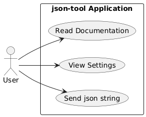
The overview functionality of the application is a way to understand what the application is doing and what it offers. Other diagrams are used to zoom in, for example, we can use the sequence diagram to understand what happens when the user sends a json string to the application.
@startuml
'This PlantUML code will be rendered soon. Meanwhile, you can check the source:

actor User
participant App
participant Router
participant Editors
participant PersistenceContextProvider
participant ThemeContextProvider
participant SettingsContextProvider
participant DefaultLayout

User -> App : Open Application
App -> Router : Initialize Router
Router -> PersistenceContextProvider : Provide Persistence Context
PersistenceContextProvider -> ThemeContextProvider : Provide Theme Context
ThemeContextProvider -> DefaultLayout : Render Layout
DefaultLayout -> SettingsContextProvider : Provide Settings Context
SettingsContextProvider -> Router : Render Routes
Router -> Editors : Render Editors Component
Editors -> User : Display JSON Editor Interface
@enduml
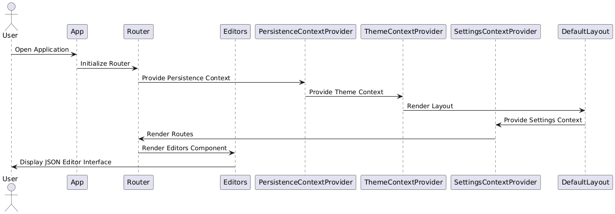
Note that the representation helps to understand the different calls going on in the application, in this case a reactjs one. Before doing any coding, or experimenting with the code, we can explore alternatives in the diagram first.
Benefits and Results
The implementation of PlantUML has yielded several positive outcomes:
- Understanding: The visualizations provided clear insights into system behaviors, aiding comprehension for both developers and stakeholders.
- Communication: Clearer communication among team members ensured alignment on the system’s architecture from the outset.
- Reduced Development Time: Early detection of potential issues streamlined debugging and improved code quality.
Lessons Learned
Through this experience, I have learned that while UML might not always be popular as traditional documentation methods, it offers unique benefits that can enhance productivity and collaboration. Leveraging tools like PlantUML empowers teams to adopt a more structured approach to understanding complex systems early in the development cycle.
Conclusion
My journey with PlantUML has proven that even challenging methodologies can offer valuable insights when implemented thoughtfully. By embracing UML, we achieved clearer communication, better alignment on system requirements, and ultimately, improved outcomes. Encouraging others to explore UML despite its perceived challenges is my goal in this blog post.
To further aid readers, I recommend exploring PlantUML tools that streamline diagram creation and collaboration, such as those that support version control and sharing, ensuring seamless integration into existing workflows. This approach not only facilitates understanding but also enhances team productivity by providing a unified method to manage system architectures from the outset.
In conclusion, while UML might be less traditional, its potential for enhancing software development practices is undeniable. By embracing this tool, we can unlock new levels of clarity and collaboration, ultimately enriching our development processes.
References
- Guedes, G. T. A. (2018). UML 2-Uma abordagem prática. Novatec Editora.
- Watson, A. (2008). Visual Modelling: past, present and future. White Paper UML Resource Page, 28.
Follow up
- Using PlantUML, create a use case diagram for a simple e-commerce application. Include actors like “Customer” and “Admin” and use cases such as “Browse Products,” “Add to Cart,” “Checkout,” and “Manage Inventory.”
- Write a PlantUML sequence diagram to represent the login flow of a web application. Include components like “User,” “Frontend,” “Backend,” and “Database.” Show interactions such as sending credentials, validating them, and returning a success or failure response.
- Research and compare PlantUML with another UML tool like Draw.io or Lucidchart. Write a short summary of the advantages and disadvantages of each tool, focusing on aspects like ease of use, integration, and version control.
- Using the example diagrams in the blog post, write a PlantUML diagram for a microservice architecture. Include services like “User Service,” “Order Service,” and “Payment Service,” and show how they interact with each other and a shared database.